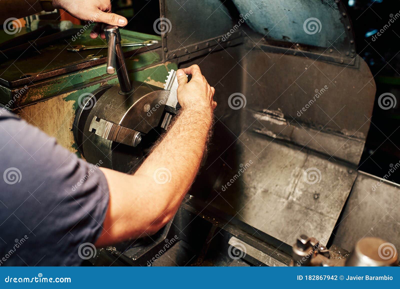
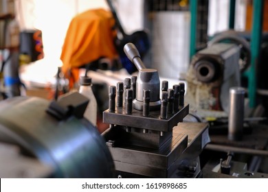
We can do different operations on the job by lathe machine. It is commonly used in the mechanical field. It makes the work easier and simpler. Mostly the simple jaws we can make on lathe machine tool. Many people know Lathe machine and saw in there laboratory or company but not aware much about parts of lathe machine and lathe machine diagram. So here we will explain what it is, how to use and their parts. The milling machine lathe attachment is attachable to an existing milling machine to eliminate the need for an operator owning both a milling machine and a lathe. It is designed to be mounted to the side of the milling machine and to be used without disturbing a setup in the associated vise. Importance of Lathe Machine in Engineering Field and its usage Jahnavi Madireddy. Parts of Lathe Machine. Ntroduction he lathe, probably one of the earliest machine tools, is one of the most versatile and widely used machine tool, so also known as mother machine tool. An engine lathe is the most basic and simplest form of the lathe. (17) 17 product ratings - 7' x 14' Mini Metal Lathe 550W Precision Variable Speed 2250 RPM 0.75HP. VERY NICE CONDITION ORIG SOUTH BEND 9 10K LATHE 4' BED QUICK CHANGE LEAD SCREW. $46.70 shipping. Logan Lathe 5C Collet Spindle Adapter # 1055-1, 2 1/2” L, 1 5/16” Dia., See Desc.
Lathe Machine:
The operations performed in a lathe can be understood by three major categories.

(b) Operations which are performed by holding the work by a chuck or a faceplate or an angle plate are:

Lathe Controls The Mechanical
Related posts:
Precision and high repeat accuracy for individual parts and small series manufacture. Made in Germany.
- Z-axis and X-axis with recirculating ball spindles and two powerful step motors.
- Control unit for connecting to PC or laptop with activation of the main spindle and the step motors.
- Including user-friendly and WINDOWS® compatible software (see description below).
High quality RÖHM precision 3-jaw lathe chuck. Witt Ø 100mm.
Powerful condenser motor with 550W.
Multiple steel holder with height-adjustable holder elements.
Step motor 1.8A for travel distance 70mm.
Recirculating ball spindle for the X-axis with 2.0mm inclination.
Recirculating ball spindle for the Z-axis with 4mm inclination.
Step motor 1.8A for travel distance 300mm.
CNC control of Z-axis and X-axis enables precise turning, facing and longitudinal turning of steel and non-ferrous metal.
Axes drive with powerful step motors and recirculating ball spindles (no backlash). For facing and longitudinal turning, for turning balls, radii and any freely formed contours made of steel and non-ferrous metal. Work piece machining is effected automatically by software and can be reproduced as often as required.
Otherwise the mechanical design is almost identical to the proven PROXXON lathe PD 400: Solid, cross-braced cast iron bed with ground and wide legged prism guide for apron and tailstock ensure vibration-free working and optimum precision. High quality 3-jaw lathe chuck (Ø 100mm). 6 spindle speeds (80 - 2,800/min) are provided via belt drive. Including rotating centre MK 2 and tailstock chuck. With quick-change tool post with 2 holders (with stop and height adjustability).
Complete with recirculating ball spindles, powerful step motors and the required limit switches, the CNC control unit, all necessary connecting cables and WINDOWS® compatible software on CD-ROM.
NO 24 500
- Precision 3-jaw lathe chuck as per DIN 6386 (Ø 100mm).
- Powerful condenser motor with 550W.
- Multiple steel holder with height-adjustable holder elements.
- Step motor 1.8A for travel distance 70mm.
- Recirculating ball spindle for the X-axis with 2.0mm inclination.
- Recirculating ball spindle for the Z-axis with 4mm inclination.
- Step motor 1.8A for travel distance 300mm.
Double roller bearing recirculating ball spindle paired with powerful step motor driven in micro-step guarantee high machining precision and repeat accuracy.
PROXXON CAD/CAM software for WINDOWS®
Brief description of software and hardware:
The software is harmonized with mechanics, motors and the control unit of the CNC machine, thus offering the optimum performance.
The CNC control unit controls the step motors of the machine. The PC software provides the machine with the geometry information for travel of the tools (via RS 232 interface). This means that the control unit is the interface between software and the mechanics of the machine.
Powerful micro processors and accordingly dimensioned step motors and phases ensure that the motors always provide enough power for any machining processes. Two freely usable output relays in the casing of the control unit provide facilities for control of additional functions, e.g. a working lamp. Including connection cables with suitable plugs and built-in power supply for connection to 220 - 240V.
Simple creation of work piece geometry
The CAD window is displayed when the programme starts. The work piece contour is created in the familiar WINDOWS® environment. Numerous auxiliary aids help during programme operation, which supports both coordinate entry (absolute and relative) in addition to mouse use.
Technology information is allocated to every drawing element. This makes, for example, different processing speeds and manual tool replacement possible.
Read-in of existing files in .dxf format is possible as well.
Automatic generation of CAM data
The finished drawing of the tool is converted, by a mouse click, into the instruction set for the machine. So, machining can be started immediately. The instruction set generated in this way is in accordance with DIN/ISO 66025 and can be manually edited and exported. Conversely, the system also permits importing or complete self writing of data sets.
Software update for precision lathe PD 400/CNC
CNC simulation
If requested, the travel distances of the tool are simulated in the graphic window. In this way, faults in the programming can be recognised in time.
Manual work
The handwheels are replaced with the step motors of the CNC machine. Nevertheless, manual machining is possible with the help of cursor buttons, since the step motors can be operated manually.
Software installation
The PC software is supplied on a CD ROM. The problem-free installation is effected under WINDOWS® as usual.
Note:
PC or laptop are not part of the scope of delivery. Minimum requirements for the hardware: Pentium processor with 400 MHz frequency (or comparable), high-quality graphic card (64 MB RAM) and at least 40 MB free hard disc storage.
Technical data:

| Power supply | 220 - 240V / 50/60Hz | ||||
| Drive | Condenser motor with 550W | ||||
| Spindle drive X-axis | Recirculating ball spindle with 2.0mm inclination, flank diameter 8mm. Step motor with 1.8A and 50Ncm dwell moment; travel distance: approx. 70mm | ||||
| Spindle drive Z-axis | Recirculating ball spindle with 4.0mm inclination, flank diameter 12mm. Step motor with 1.8A und 50Ncm dwell moment; travel distance: approx. 300mm | ||||
| 6 spindle revolutions | 80 - 160 - 330 - 660 - 1,400 - 2,800/min Selectable with switch (two-stage) and by placing drive belt. | ||||
| Control of step motors | via CNC control unit (included in scope of delivery) | ||||
| Software | on CD-ROM, installation under Windows 98, Windows 2000, Windows XP, Windows Vista and Windows 7 | ||||
| Drive connection | via RS 232 interface (or: use of a USB adapter), connecting cables to PC included in scope of delivery | ||||
| Sizes |
| ||||
| Total weight | Machine: approx. 45kg / Control unit: approx. 4kg | ||||
Lathe Mechanic
Computer with software
RS 232 interface
MCS-multicontroller
Step motor (X-axis)
Step motor (Z-axis)
Switch X-axis
Switch Z-axis
- Computer with software
- RS 232 interface
- MCS-multicontroller
- Step motor (X-axis)
- Step motor (Z-axis)
- Switch X-axis
- Switch Z-axis
Thread cutting device for the lathe PD 400/CNC

A complete attachment kit with rotary encoder for the main spindle, belt pulleys, synchronous belts and all required accessory parts.
The software of the PD 400/CNC has already been programmed accordingly: Available now are the standard male threads M 1 to M 42. Special threads of any type (e.g. inch threads) can be manufactured as well with different pitches and thread depths. Including detailed assembly instructions.
NO 24 506
Self-centering 3-jaw chuck
Identical to the lathe chuck of lathe PD 400. Capacity through reversing chucks 3 - 100mm.
NO 24 407
Self-centering 4-jaw chuck
The jaws are not independently adjustable, i.e. they are self-centering. High accuracy. Chuck diameter 100mm.
NO 24 408

Collet attachment with collets for PD 400
For accurate use on round components. One hardened collet each hardened collet 2 - 3 - 4 - 5 - 6 - 8 - 10 - 12 and 14mm are included. Concentric accuracy better than 0.02mm, much better than a chuck. One soft collet for making a custom size yourself. The included collet attachment is mounted in the place of the headstock chuck. Supplied in a wooden box.
NO 24 419 complete
Tool post
Including two holders. Provides quick tool changes with easy height adjustment. For turning tools 10 x 10mm.
NO 24 415
Individual quick-change holder
Fits the tool post of PD 400.
NO 24 416
Die holder for round die.
For threads M 3 - 4 - 5 - 6 - 8 and 10.
With holder Ø 10mm for mounting in the tailstock drill chuck of the lathe. The holder is held by hand while cutting the threads. Neatly packed in wooden box with sliding lid.
NO 24 082
Cutting tools of high quality cobalt HSS steel, ground.
Five piece set
One each roughing out, parting, finishing cut, left and right cutter. Comes in wooden box with sliding lid. 10 x 10 x 80mm.
NO 24 550
Three piece thread cutting set
One cutter for external thread , one for internal thread (both ground to 60°, metric), one general cutting . Supplied in wooden box with sliding lid. 10 x 10 x 80mm.
NO 24 552
Cutter set with tungsten inserts
Three holders (90mm long):
for roughing out;
for longitudinal work;
for 90mm boring bar, holes from 12mm.
Standard tungsten inserts, 55°, plated (commercially available version). Three additional inserts securing screw and key TX 8 are included. 10 x 10mm.
NO 24 556 complete
Tungsten disposable tips (not depicted)
For the holders as described above.
NO 24 557 Ten piece set
Three piece centre drill set
Made of HSS steel. DIN 333 (type A) 60°. Complete set centre drills with sizes of 2.0 - 2.5 and 3.15mm.
NO 24 630
HSS boring tool set, 6 pieces
One each cutter for 60 degree (metric) and 55 degree (Whitworth) inside threads, 1.3mm - 2.65mm and 4mm. Shaft of Ø 6mm. Length 95mm. The cutters are held by a tool holder (9 x 9mm) that mounts to the tool post of either PD 230/E, PD 250/E or PD 400. Comes in wooden box with sliding lid.
NO 24 520
